The rise of networking form the 1980’s onward may be considered the main driving force of the invention of enterprise architecture, itself a follow-up on what was until then known as system architecture. On the eve of the rise of the ‘softwarification’ of infrastructure (software defined data centers, software defined networks) and the ongoing impact of Cloud-architecture, it is time to look into the modelling of networking infrastructure some more.
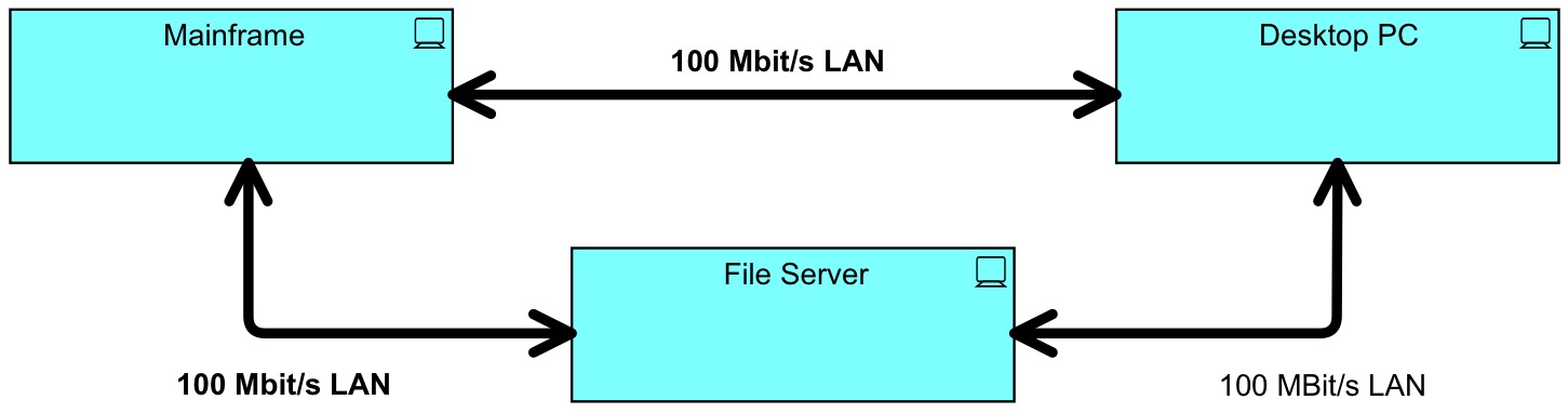
ArchiMate has two specific concepts for networking: Network and Communication Path. Network is the element that represents physical networking, as the standard explains, and it gives the following example:
 Actually, the standard displays it differently, with the middle Network element and both Associations replaced by an arrow on two sides, but my (ArchiMate-compliant) modelling tool does not support that notation (though I can trick it graphically, see below). Probably no user of that (leading) tool ever has used that notation, which tells us already something.
The network gets rather limited attention in the ArchiMate standard, which says:
A network represents the physical communication infrastructure. This may comprise one or more fixed or wireless network links. The most basic network is a single link between two devices. A network has properties such as bandwidth and latency. It embodies the physical realization of the logical communication paths between nodes.
And that, more or less, with the example above, is it. It is noteworthy that the inventors of the ArchiMate enterprise architecture modelling language (young academics and experienced IT-professionals) in the early 2000’s almost did not pay attention to networking at all. The pre-1.0 ArchiMate document is almost completely silent about it, just mentioning the physical and logical communication going on in the infrastructure. It is understandable though, because at the time networking was still considered unimportant low level structure of the enterprise’s architecture. In the Mastering ArchiMate book, I also spend very little time on networking concepts of ArchiMate, because I see them used seldom in enterprise architecture modelling. I also mention another argument in the book to ignore networks that is really ripe for the scrap heap: networks are ‘just there’. These days, with the emergence of the Cloud computing hype & reality, suddenly the design and use of networks is becoming an essential part of enterprise reality and complexity. One learns…
In the days that ArchiMate was invented, network engineers ranked absolutely lowest in the corporate IT hierarchies and they probably were not sent to important enterprise architecture language creation meetings, so their knowledge did not end up in the spec; but I digress. Another digression: the example of the mainframe being connected to the desktop PC is also telling about the world of those who invented the language. On the other hand, a mainframe with terminals is essentially a basic cloud solution, so they came from really innovative environments, right? (Actually, the mainframe example was introduced by The Open Group in the 1.0 version of the standard, the original pre-1.0 ArchiMate document (Concepts for Architectural Description) gave no example at all).
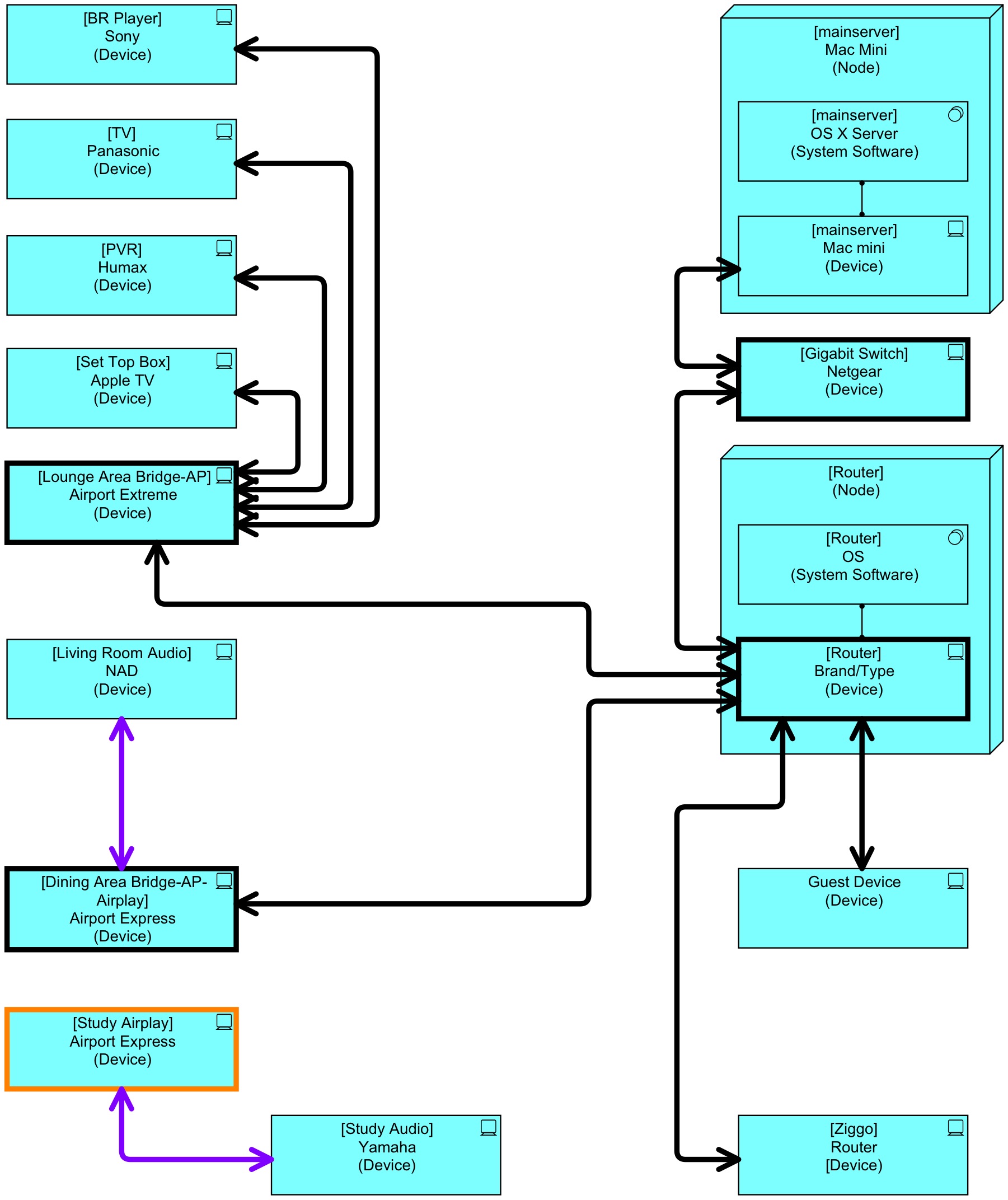
What happens if you actually try to use this concept? I took a very simple architecture, namely the IT-infrastructure in my home to see where this would lead me. So, here is the network infrastructure that is at the heart of my infrastructure at home, modeled with ArchiMate’s Network concept. This is not complete (e.g. my VoIP telephone switch is not included, nor are network printer, MacBook Pro, iMac, iPads, iPhones, iPods, et cetera — yes this is an Apple environment).

There are many networks in my home. First, there is the outside network (fat red border), my network provider who connects my home directly to the internet. I run my own server for mail and such, the provider (Ziggo) is just used to deliver raw internet to my router.
My router provides NAT, firewall and three internal networks:
- the Wifi Guest Network (SSID2, which can only talk to the outside world, it is separated from my internal network)
- a Wifi Network for own use (SSID1)
- a Gigabit ethernet network.
The Gigabit ethernet ports are connected to
- The VoIP telephone switch (which uses DECT networking to connect to hand sets), not shown
- a Gigabit ethernet switch in my study (see below)
- an Airport Express in the dining area of my living room
- an Airport Extreme in the lounge area of my living room
The Gigabit ethernet switch in the study connects to my server and other devices (not shown), such as a networked laser printer, a NeXT cube, an iMac, a MacBook Pro (when connected through ethernet, it can also connect through Wifi), a Mac Mini G4 (for older PPC software)
The Airport Extreme has two functions:
- It provides an alternative access point for the internal Wifi (same SSID, same password, which is how larger organisations do it too, you can walk around with your device, using the ‘same’ Wifi network, but the device connects automatically to the strongest access point);
- It has an ethernet switch of a couple of ports, thus creating a second ethernet network segment;
- It is in bridge mode, it just passes IP through between all ethernet ports and the Wifi network, so it acts as a switch, not a router.
The Dining Area Airport Express has three functions:
- It provides another access point for the same Wifi (SSID1) just like the Airport Extreme. This was done because one upstairs room had really bad reception because the signal of the Router’s Wifi had to travel through a few meters reinforced concrete to get there.
- It acts as bridge between the ethernet and the Wifi
- It is connected via audio cable to the audio setup, so it acts as Airplay device (receive streamed digital audio from Apple devices, convert to analog and pass on to the audio output). This is shown as an ‘analog audio’ Network, coloured purple.
So, logically, I have two internal ‘computer’ networks, a Gigabit ethernet wired network (that extends to the study and the living room) and a Wifi network with three access points (once central and two in the living room). This is shown by nesting the actual networks inside larger aggregations. Those aggregations are aggregated in my overall Network element for the entire network.
The Study Airport Express just acts as Airplay device, it does not provide a Wifi or act as bridge, it connects to Wifi SSID1 as a client. Note that it is not modelled to connect to all three Wifi networks, but to the aggregation of those, I do not know which access point it actually connects to.
So, home free? Not really.
First, let’s talk about what “100 Mbit/s LAN” means. The standard talks about it being a ‘physical communication infrastructure’ which has bandwidth and latency. Now, if I connect a server in one data center to another one in another data center, e.g. for failover or fallback (not an uncommon scenario), is there a physical communication infrastructure? It has bandwidth, it has latency. Is it allowed to have switches in between, is that still ‘physical communication infrastructure’? Or is every cable between two devices to be seen as a separate network? If the Network element is only to be used to connect exactly two Devices, exactly in the way a relation-type concept would, we would get the following (this, by the way is the alternative notation for a Network element in ArchiMate — I tricked my tool):

Fine, but what if there are three devices on that network that all can freely reach each other? We would have to model:
And with four devices, it becomes:

It gets rather messy soon, and in reality there are generally many more devices on a network. So, associating each and every one of those with a single Network element is obviously more elegant:

This almost looks like the Network thing in the middle is a network switch or patch box with the Devices attached to it via cable. The notation of Network as an element also has a major advantage: you can split the network model up over multiple views by re-using the Network element in each view.
That “100 Mbit/s LAN” network may consist of several segments connected via multiple switches. In the case of my home, above, I have modeled the physical communication structure as multiple Network elements. That way, it becomes clear that if the Airport Extreme goes down, there is no Network between Router and TV. But actually, I don’t need the Network elements for that. If I model the same view with the relation-type Network graphics, I get:
I had to replace the open-ended Networks with Devices (Guest Device and the router from my internet provider). I coloured the analog audio ‘network’ purple again. And I left one problem area unsolved: how do I show that the Study Airport Express is connected to the Wifi? Draw Network relations to all access points? Messy. Find out which access point it normally uses? Brittle. So, this link-style network-concept in ArchiMate has issues.
In the first picture of my home network, above, I have connected the Airport Extreme to the Router ethernet Network. Why not connect the Router to the Airport Extreme ethernet Network? I used the router network, because that is more or less the hierarchy of the physical networking in my home. In fact, such switching devices normally have one input port and several output ports. But there is an issue with the modelling possibility that ArchiMate provides with the Network concept: how do I know that the Airport Extreme ethernet extends the Router ethernet and not the other way around?
What is a Network?
Networks are getting more attention, these days, with Security and the Cloud as drivers and new innovations such as Software Defined Networks on the horizon. When ArchiMate was concocted, nobody paid much attention to networking, it was seen as a basic and generally not very complex subject that existed at the level of power and water. Low complexity, low status and low attention. The ArchiMate language reflects that. The concept is there, but it is far from clear, the examples were missing (now we have one) and it seems to have been added because it had to be there, but deep networking know how seems not to have played a role. Still not, I think, network architects are far removed from enterprise architects.
Furthermore, both ArchiMate’s forms of the Network concept, the ‘relation form’ and the ‘element form’ lead to questions. If we have the pattern Device A – NetworkRelation X – Device B – NetworkRelation Y – Device C, would we not want to draw derived conclusions about the networking between Device A and Device C? If we use the ‘relation form’ we cannot, there is no such derivation in ArchiMate (but we still can as humans, of course). If we model it as elements, Device A – Association – Network X – Association – Device B – Association – Network Y – Association – Device C, we can formally derive an Association between Device A and Device C, but not very telling or helpful, the idea of a network is lost.
Using the ‘relation form’ of the Network concept turns the Network concept a bit into a thing like a cable (a direct link), and this breaks down when the network is broadcast-like. Maybe, those concepts would have been better: a Link relation and a Bus element. You could then Link a Device to a Bus, or to another Device. And we already have a good relation we can reuse for linking: the Flow relation.
I have so far ignored ArchiMate’s Communication Path concept. Where a Network can be seen as communication infrastructure that just transports bits and bytes from Device to Device, Communication Path is meant to be used for more high-level concepts such as ‘messaging’.
When all these switches are turned on in my house there is a direct link between server and TV and between all the others: if one floods the Network, all suffer. The relation-style hides that. Conclusion for now: use the element-form for networks and all Associated ‘share’ all the data that is on the same network, i.e. if they are associated with the same network.
All of this is far from satisfactory. If they are not already so, network architectures are going to become as complex as application architectures in the foreseeable future. And I suspect that ArchiMate’s networking concepts are not up to the task. Is there a better way to model networks in ArchiMate as ArchiMate is now? I think there may be, but that will have to wait for a next post.
Too much detail?
It is often argued that you should not do architecture at such a detail level. But this example could also have been made at a ‘low detail’ level, with elements representing large pieces of infrastructure elements, e.g. a Network element for an entire campus network with thousands of computers attached to it and a data center network with hundreds or thousands of servers.
More importantly, though, I think that ‘detail‘ must be as much as possible the choice of the modeller, not the language. I can put a few simple statements on a presentation slide and many difficult sentences in a document, and they both come from the same language. Besides, the standard mentions a single link between two devices as a most basic use for the Network concept, so for now and later: let’s stop arguing about the level of detail, a true enterprise architecture language must be able to handle both low and high detail levels, because sometimes you need one, sometimes you need the other. Abstraction must be a choice. An enterprise architecture language that is only fit for simple high-level pictures is like a natural language that can only be used to write Powerpoint slides (not counting those horrible powerpoint presentations that are more written documents); but I digress again, as usual.
A new story about the modelling of networking in ArchiMate 3.1 is available

Very instructive, practical, original, and focused example. What’s the next step in diagramming the Cloud, though?
LikeLike
Hi and thanks for this, but where should I find the Network Element box for dragging into my diagramme in Archi version 3.0.0?
Thanks!
LikeLike
@so – The Network element is in the Palette. It’s coloured green.
LikeLike
High level network modelling is an aspect of ArchiMate I have always struggled with. When working on infrastructure views I often want to show that a device initiates a connection to another device (often a 3rd party device) over a particular network port, this can then drive firewall requests later on etc. The ‘relation form’ is more useful here with a label displaying the port number. For internal network views the ‘element form’ is more suitable, like the suggested ‘bus’ element.
When it comes to arrows, this can also cause confusion as the direction of the connection (important from a firewall rule point of view) can be different from the data flow and these need to be represented separately.
I have previously used the Access relation for network connections (although my tool no longer allows this) as it allows you to specify the direction i.e. ‘Read’, ‘Write’ & ‘Read/Write’.
As outlined, technology is moving on and our modelling tools need to move with it, it would be really good if the next version of the spec catered for some of these concepts.
Any other suggestions for modelling the direction of network connections?
LikeLike
Hi there, what I do is use an association between a nodedevice and the network object to represent what IP network it is in, and use the network “connector” between nodes to represent the details needed for firewall rules.
LikeLike
One other issue I ran into when I tried to apply this to my home networking was my desire to have the port numbers and the cables in the model.
I have taken to modeling a PC talking to a NAS via a WiFi Router as:
device – association – network – association – device – association – network – association – device
Which breaks down like:
device = PC
association = PC WiFi “Port”
network = WiFi 2.4GHz Network
association = Router WiFi “Port”
device = Router
association = Router Ethernet Port #1
network = Ethernet Cable #1
association = NAS Ethernet Port #1
device = Nas
This seems compliant. I am just noting how the association takes place, which is via the port. It seemed a lot more natural to utilize an interface that was part of the device, but that doesn’t seem compliant unless we are wanting to think of the ‘sending and receiving packets’ as a separate infrastructure service which has it’s own interface that they would connect to, etc, etc.
My plan for my exercise was to simply portray physical infrastructure, then layer on the details. Start with a L1/2 type diagram, devices/networks/associations, then layer on L3, nodes/communication paths/services/functions.
LikeLike
An association is by definition compliant, it is the one relation you may use between any two elements.
Port number is information that typically fits in the Infrastructure Interface concept. Even a cable could be an interface.
If you think about routers switches, it becomes also interesting to look at logical constructs at L2 level, such as switch/bridge (i.e. eth(2,3,4) = switch(0); eth(0)+switch(0) = bridge(0). It is however likely that modelling at this level will not be functional for large networks where everything is going ‘software defined’. Too much volatility with respect to the model.
LikeLike
I suppose my use of the word ‘compliant’ may be incorrect here. Maybe I should just say ‘more clear’ as the association is definitely ‘compliant’ as you noted. I am using these home networking style diagrams to introduce people who aren’t familiar with Archimate to its use.
As mentioned in the ‘Too much detail?’ section, it’s questionable the value of this type of modeling within an enterprise. I think the value is in bridging the gap for individuals trying to migrate from an informal tool like Visio. Those types of individuals are usually Technology people and the most frequent question I get from them is, “How can I convert this Visio Diagram?” The Visio diagrams in question almost always seem to have IP Addresses, Network Ports, and maybe even Cables and Physical Ports on devices.
I wish the standard came with a more extensive networking diagram example.
LikeLike
I was wondering if you had had any thoughts on the next installment of this post. Our team is just about to start modelling networks and I would be interested in any patterns you are using.
LikeLike
Hi Peter, not yet I’m afraid (been busy with other things).
My approach would be to use the standard TI elements and relations in ArchiMate (Nodes and Infrastructure Services and such) and maybe without the Network and Communication Path elements (though Network might still be useful for netwerk segments or zones). But you would want the different elements visible as network engineers are used to (such as routers, switches, etc. with their standard icons) such as you see in the common graphical representations. That means expanding the ArchiMate model with specialisations of Node and implementing that in your tool of choice.
LikeLike
It’s been 5 years in the making, but a new article about modelling networking is available (see bottom of this article)
LikeLike